Introduction
Throughout our A-level course so far, we have used a particle model. We will now start to treat objects as a rigid body, extending the model to give objects size, but continuing to assume that they are inflexible so do not bend or deform when forces are applied to them.
We now consider the moment or turning effect of forces. To do this we need to calculate the centre of mass of standard shapes and composite bodies. We will also look at when objects are on the point of breaking equilibrium, causing them to slide or topple.
Moment of a Force (the word “moment” is interchangeable with “turning effect”)
The moment of a force F, about a point O, is F x d, where d is the perpendicular distance from the point O to the line of action of the force F. The moment of each force is measured in Newton metres (Nm). If the perpendicular distance between the force and the point O is zero, then it contributes no moment.
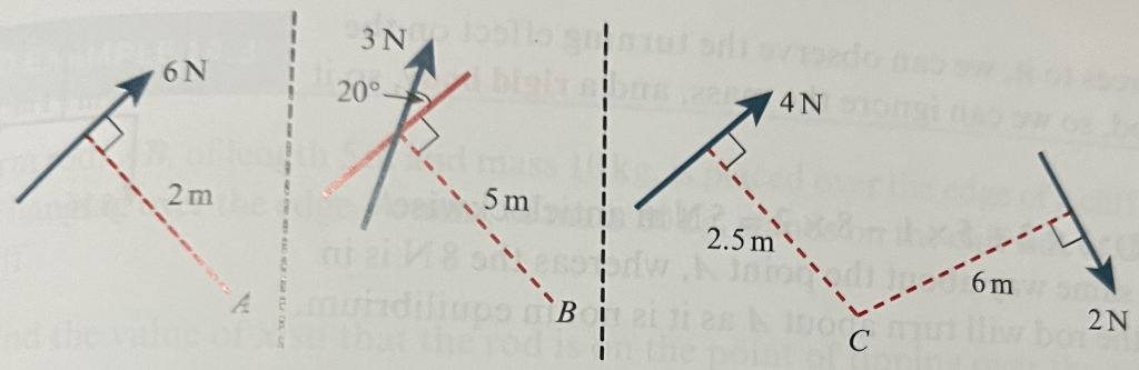
In the first diagram above, the moment of the 6N force about the point A is 6×2, so 12 Nm.
In the second diagram, we need to find the component of the force acting perpendicular to the line through B, which is 3cos20. So the moment is (3cos20) x 5, so 15cos20 or 14.1Nm.
The third diagram shows two forces applying a moment to point C. Both act in the same direction, i.e. clockwise, so they are combined by addition. The total moment on point C is 2×6 + 2.5×4, so 22Nm.
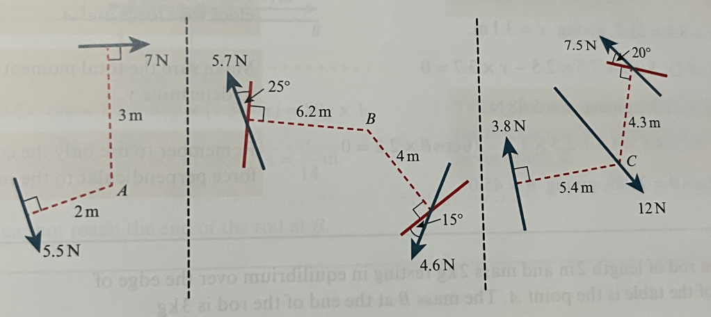
Worked Example
Calculate the moment in each of the examples below, specifying whether it acts in a clockwise or an anticlockwise direction:
Moment on a light rod
We can select a point on a rod and calculate the moment of forces on that point, modelling the rod as light and as a rigid body.
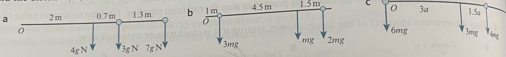
Worked example
In each of the diagrams below, a light rod is pivoted at a fixed point, A and we want to find the unknown values such that the rod will have a zero moment about A:

Moment on a rod that has a weight
Below we consider a uniform rod with length 2m and mass 2kg that rests in equilibrium, extending over the edge of a surface. The edge of the surface is point A, and a mass of 3kg holds the rod down at point B:

As the rod is modelled as uniform, so its weight acts through its centre, as marked on the diagram below. If there was no mass at B, then taking moments about A would give 
The mass at B causes a moment of 
Worked Example
A uniform rod AB, of length 5m and mass 10kg, is placed over the edge of a cliff such that B hangs 4m over the edge of the cliff. A man of mass 80kg stands on the cliff side of the rod at a distance of xm from the edge of the cliff.
(a) Find the value of x so that the rod is on the point of tipping over the cliff;
(b) The man now stands at A and a boy of mass 35kg walks across the rod towards B. Can the boy walk all the way to the end of the rod?
Exercise 1


Exercise 1 Answers
- 1.05kg
- 0.333kg
- 10/3
- (a) 6.3Nm anticlockwise (b) 22.1 Nm anticlockwise (c) 36Nm anticlockwise
- (a) 46.5 Nm clockwise (b) 12.8Nm anticlockwise (c) 2.89 Nm anticlockwise
- (a) 0.119m (b) 3.8kg
- (a) x = 9.8m (b) x = 40.2m (c) x = 3.20 m

Centres of Mass Part 1: Rods and Laminas
Moments help us to find the centre of mass of an object, which we can model as the point through which all of the weight of an object acts.
Effectively, we can replace a number of forces at different distances from a point with a single force at a calculated distance from the point that represents their combined effect. We do this by measuring the distances xi of each of the masses mi from the point of reference and then calculating the distance of the centre of mass

Worked Example – Finding centre of mass of rods (i.e. in one dimension)
Find the distance, 
Extending the concept to 2 dimensions
In 2 dimensions we can find the coordinates of a centre of mass relative to two perpendicular axes of reference. We start by considering a framework or light rods with masses attached to them. Masses that are on an axis will have no turning effect on that axis.
Worked Example: Finding centre of mass of framework of rods (i.e in two dimensions)
A rectangular framework, ABCD, comprises four light rods, with masses on the rods at the points as per the diagram below:
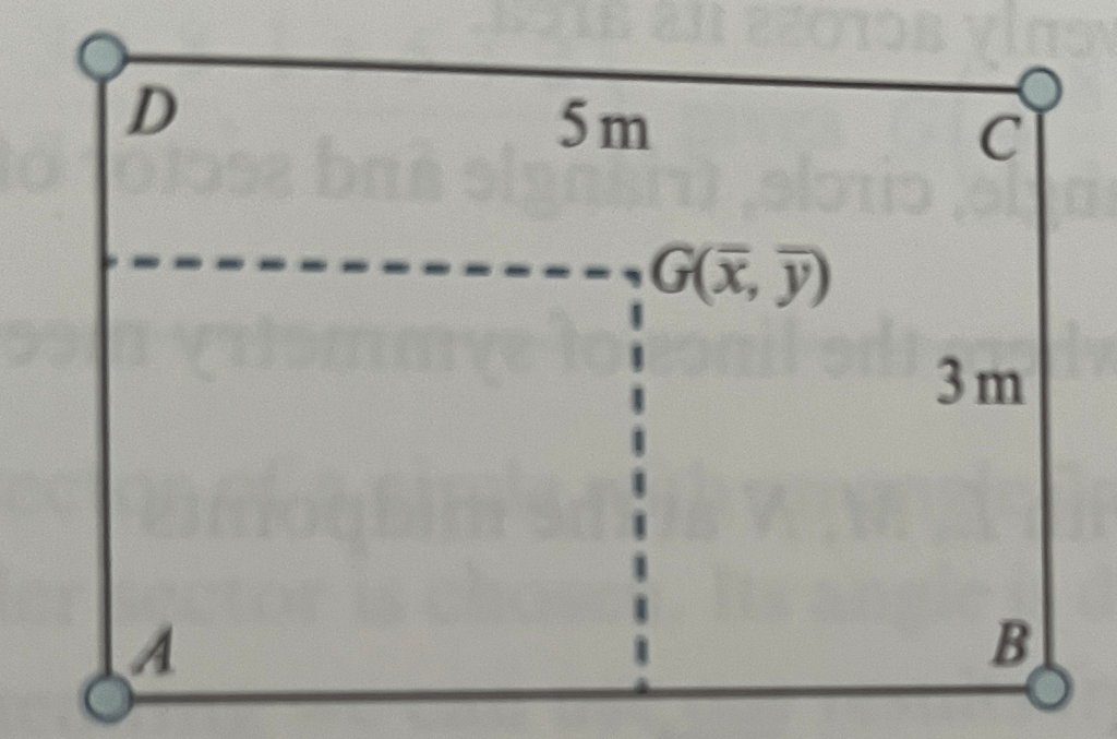
In each of the below cases, determine the coordinates of the centre of mass. Use AB and AD as axes, with A as the origin:
(a) 2kg at A, 4kg at B, 7kg at C and 2.5kg at D;
(b) 5kg at the midpoint of AD, 6kg at B and 4kg at E, where

(b) 6kg at A, 3kg at the midpoint of AB, 8kg at B and 10kg at F, where

Centre of Mass of standard 2D laminas
We now extend from frameworks of rods to consider laminas. These are effectively objects with negligible depth whose weight is spread evenly across their area.
Rectangle: The centre of mass is in the centre, where the lines of symmetry meet.
Triangle: If the three vertices of the triangle are at (x1,y1), (x2,y2) and (x3,y3), then the centre of the mass is at

Worked Example: Triangular Laminas
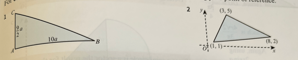
Find the centre of mass of each of the below triangles, stating your point of reference:
Centre of Mass of 2D Sector Laminas
The centre of mass of a sector-shaped lamina subtending an angle of 2𝛼 is 
Worked Example 2D Laminas – Sectors
Determine the centre of mass from the centre O of a sector of radius r with angle: (a) π/2 (b) π
Centre of Mass of 2D Composite Laminas
With more complex shapes we can break them up into standard shapes in order to find the centre of mass. We use 𝜌 to represent the mass of the composite shape per unit area. Multiply the areas of each of the shapes by 𝜌 to get the mass of the whole lamina (which is effectively what we will divide by
Worked Example Composite Laminas
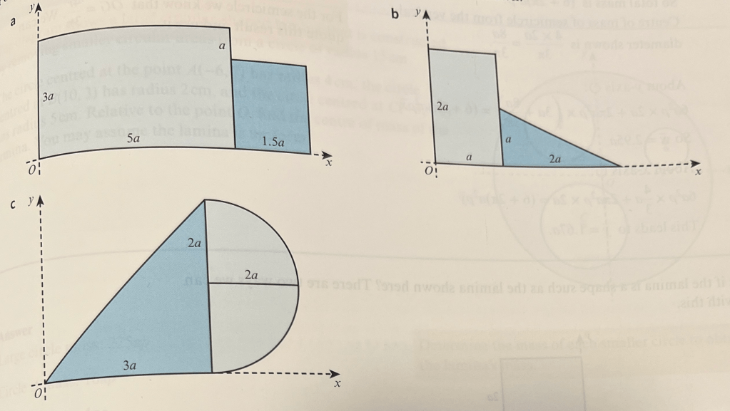
Calculate the centre of mass of each of the below composite shapes relative to the axes shown:
In the following example we use subtraction, finding the centre of mass of the overall shape and then subtracting the centres of the mass of the parts of it which are absent
Worked Example Composite Laminas with Parts Missing
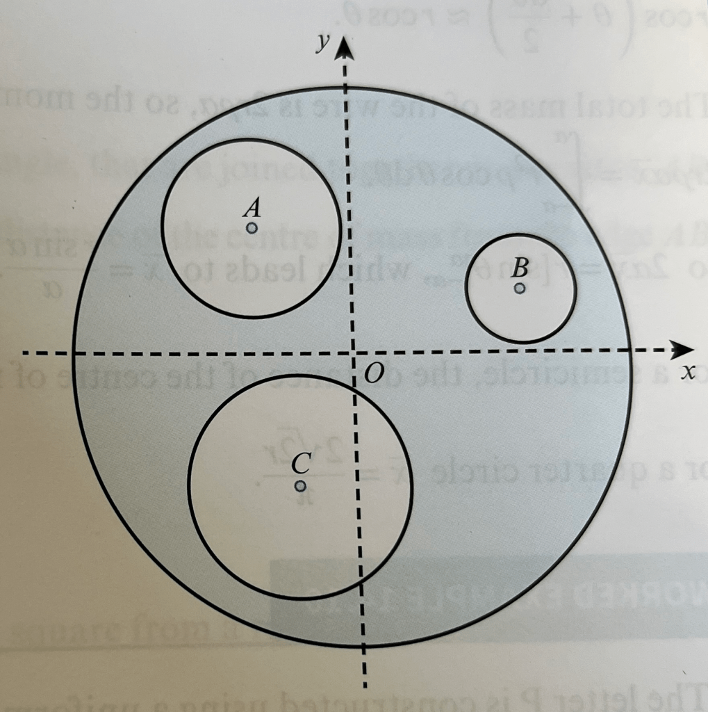
The diagram below shows a circular shaped lamina constructed by removing smaller circular areas from a circle of radius 15cm. The circle centred at point A(-6,7) has radius 4cm, the circle centred at B(10,3) has radius 2cm, and the circle centred at C(-3,-6) has radius 5cm. Relative to the point O, find the centre of mass of the lamina, assuming that the lamina is uniform.
Centre of mass of circular wire
The centre of mass of an arc of a circle 2𝛼 radians from circle centre O has centre of mass 
Worked Example
A letter P is constructed using a uniform straight piece of wire of length 4a joined to another piece of uniform wire bent into a semicircle of radius a. If the semicircular piece of wire is three times as dense as the straight wire, then find the position of the centre of mass 
Exercise 2
Exercise 2 Answers
 from AB,
  from AC


Centres of Mass of Solids
Regarding 3 dimensional shapes, we will consider a cone and a hemisphere
Cone: The centre of mass of a right circular cone of height h and base radius r is given as 
Worked Example: Cones 1
A solid uniform cone of height 3a and base radius a has a smaller similar cone removed from it. The smaller cone has height a. The resulting shape is known as a frustum. Find the centre of mass of the frustum, measured from the smaller of its two plane faces.
Worked Example: Cones 2
A solid uniform cylinder, of radius 2a and length 6a, has a cone of height 3a and base radius a removed from it. The cone removed has its axis of symmetry coinciding with that of the cylinder, and the plane face of the cone lies in the same plane as one end of the cylinder. Find the centre of mass of the remaining solid when measured from the opposite plane face of the cylinder.
Hemisphere: The centre of mass of a solid hemisphere with radius r is given as 
Worked Example: Hemispheres
A solid uniform cylinder of radius 3r and length 6r is connected by one of its plane faces to a solid uniform hemisphere of radius 2r. Their lines of symmetry coincide and the density of the hemisphere is twice that of the cylinder. Find the distance of the centre of mass of the solid from the plane face that is at the opposite end from where the hemisphere is connected.
Worked Example: Balancing
A solid uniform hemisphere of radius 2r is joined to a solid uniform cone of height h and base radius r. The cone and hemisphere have their plane faces joined together. At the join, their lines of symmetry also coincide. If the cone is twice as dense as the hemisphere, find a relationship between h and r so that the shape can balance when both the plane faces are vertical.
Exercise 3
Exercise 3 Answers


Equilibrium, Sliding & Toppling
Consider a uniform ladder AB, with length 2a and mass m, resting against a smooth vertical wall and a rough horizontal floor, such that the ladder makes an angle of 𝜽 with the wall, where tan𝜽 = 3/4
We want to find the range of values for the coefficient of friction that would keep the ladder from slipping.
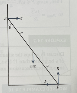
We can do this by resolving forces horizontally to give F = S and vertically to give R = mg. For the ladder not to slip, we need F ≤ μR.
Taking moments clockwise around B gives: S x 2acos𝜽 = mg x asin𝜽. So using sin𝜽 = 3/5 and cos𝜽 = 4/5, we have 


Worked Example: Equilibrium 1
A uniform ladder is placed against a smooth vertical wall and rough horizontal floor. The ladder is of length a and mass 2m. The ladder is placed such that the angle between the ladder and the vertical wall is 30°. A painter of mass 5m stands one quarter of the way up the ladder and ladder is on the point of slipping. Find the minimum coefficient of friction required to prevent the ladder from slipping.
Worked Example: Equilibrium 2
A uniform rod of mass m and length 2a is held in equilibrium by a light inelastic string of length 2a and by a frictional force due to the rod’s contact with a rough vertical wall. The angle between the string and the rod is 60°, as shown in the diagram below. The rod is on the point of slipping downwards.
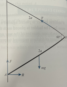
By resolving forces, and taking moments at an appropriate point, find a range of values of μ so that the rod does slip down.
Toppling
Consider a rectangular block on a rough sloping plane, with a coefficient of friction sufficiently large to prevent it from slipping. The block has dimensions a x 2a x 3a (3a is the depth of the block). The slope is slowly raised until the angle is sufficiently steep so that the object topples over. We are interested to know at what angle the block is about to topple.
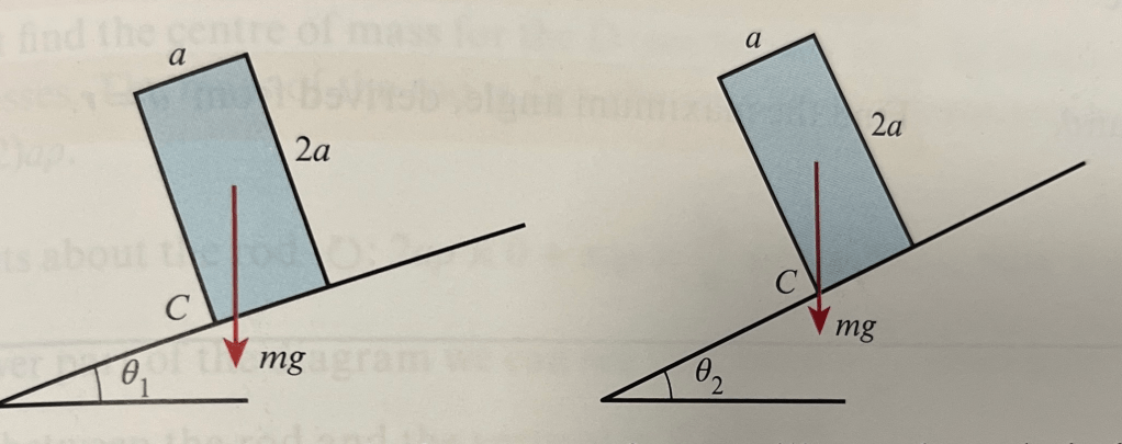
The block topples if its centre of mass is to the left of the bottom corner of the block (i.e. so in the right-hand diagram above, it is at the point of toppling).
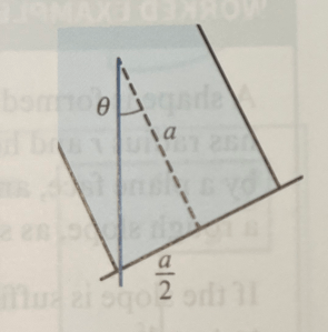
Notice that there is a small triangle that we can use to calculate the angle which will cause the block to topple, illustrated below. So the minimum angle for toppling is tan𝜽 = 
Worked Example: Toppling 1
A solid uniform hemisphere is placed on a rough slope, with its plane face against the slope. We will assume that the frictional force is sufficient to prevent the hemisphere from slipping.
If the slope is inclined at an angle of 65°, state whether or not the hemisphere topples. Justify your answer.
If it does not topple, what is the maximum possible inclination of the slope.
Worked Example: Toppling 2
A shape is formed by joining a solid uniform cylinder to a solid uniform cone. The cylinder has radius r and height r; the cone has base radius r and height 2r. The two solids are joined by a plane face, and the lines of symmetry of the two solids coincide. This shape is placed on a rough slope as shown in the diagram below. If the slope is sufficiently rough to prevent sliding, find the angle at which the shape is about to topple.

Suspended Objects
As well as considering objects on surfaces, we can consider objects suspended by a given point.
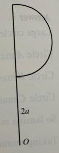
For instance, consider a letter D formed from uniform wire. We will model it by a rod of length 2a and a semicircle of radius a as shown below.

We are interested in finding, when we hang the letter D from one of its corners, what the angle will be between the rod and the vertical.
First we must find the centre of mass of the D.
The rod has mass 2a𝜌 and the arc has mass πa𝜌, so the total mass of the D is (π+2)a𝜌.
Taking moments about the rod, we get 2a𝜌 x 0 + πa𝜌 x 

Using the following diagram, we can see that 

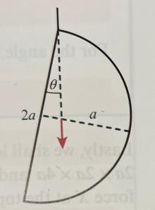
Hence the angle between the rod and the vertical is 𝜽 = 21.3°
Worked Example – Suspended Lamina
An L-shaped uniform lamina is formed by joining two rectangles together, as shown in the diagram below:

(a) Find the centre of mass of the lamina from the edges AB and AC.
(b) The shape is then suspended from point A. Find the angle between AB and the vertical.
Worked Example – Suspended Solid
The diagram below shows a solid uniform cone joined to a solid uniform hemisphere. The cone has base radius r and height 3r, and the hemisphere has radius r. The two shapes are joined by their plane faces, and AB is a diameter on that plane face.
If the density of the cone is four times that of the hemisphere, find the position of the centre of mass relative to the line AB. The shape is then suspended from point A. Find the angle that AB makes with the vertical.
Sliding vs. Toppling
Consider a cuboid with dimensions 2a x 2a x 4a and mass m, resting on rough horizontal ground.
We apply a force F at the top edge of the cuboid, which will either make it slide along the ground, or topple at O:
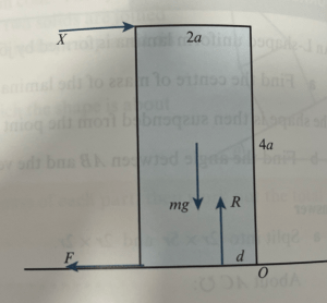
As the force X increases, the reaction force gets progressively closer to point O, which eventually will cause it to topple, if it hasn’t already started sliding.
Resolving forces gives X=F and R=mg
Taking moments about O gives X x 4a + R x d = mg x a
So

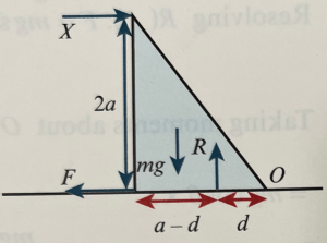
If X = 0, then d = a, so the reaction force is halfway along the edge touching the ground.
If X = mg/4, then mga = mga – mgd, so d = 0, so the block is on the point of toppling
If X = F = μR, then if μ>1/4, the cuboid will topple before sliding.
If X = mg/6 and μ = 1/8, then we get d = a/3, so the shape will not topple. As Fmax = mg/8, so X>F and the cuboid will slide.
Worked Example – Sliding vs Toppling 1
A uniform right-angled triangular prism, of mass m, is resting on a rough horizontal surface, as shown in the diagram. The triangle has sides a, 2a and 
Determine in each of the following cases whether the prism breaks equilibrium, and if it does, whether it slides or topples:
(a) X = ⅕mg, μ=3/4 (b) X = ¼mg, μ = ⅕ (c) X = ⅓mg, μ = ½
Worked Example – Sliding vs Toppling 2
A solid uniform cone, of base radius r and height 4r, is placed on a rough plane inclined at an angle 𝜽, as shown in the diagram below:
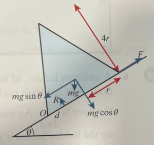
The coefficient of friction betwen the cone and the plane is 0.5. The plane is hinged at the bottom and it is slowly rotated so that 𝜽 increases. Giving a justification for your answer, determine whether or not the cone topples before it slides.
Exercise 4
Exercise 4 Answers
- 68.2°
- 29.7°
- μ≥
- 32°
- 55.8°
- a
- 0.474mg, at an angle of 82.7° clockwise from the wall
- Topples first
- (a)
. (b)


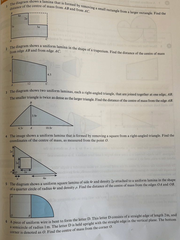
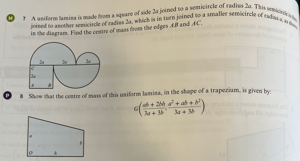
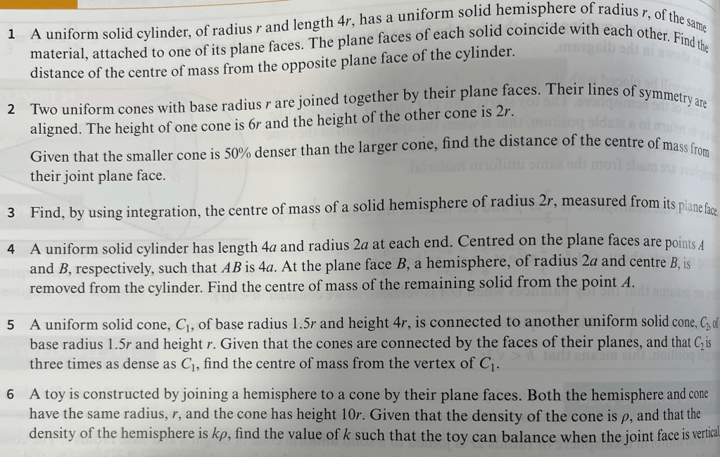
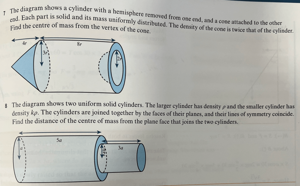
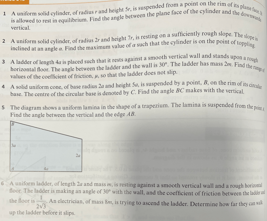
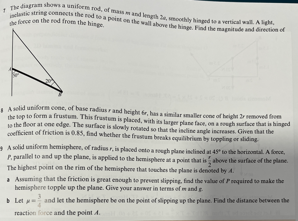
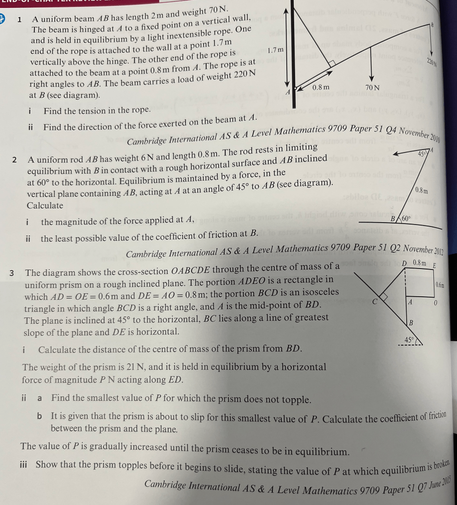
End of Chapter Exercise
End of Chapter Exercise Answers
- (i) 562.5N. (ii) 52.1° with vertical
- (i) 2.12N. (ii) μ = 0.313
- (i) 0.143m. (ii) (a) P = 2.5 (b) 0.787 (iii) P = 26.0, Proof
